|
|
|

|
SUMMARY OF THE INVENTION
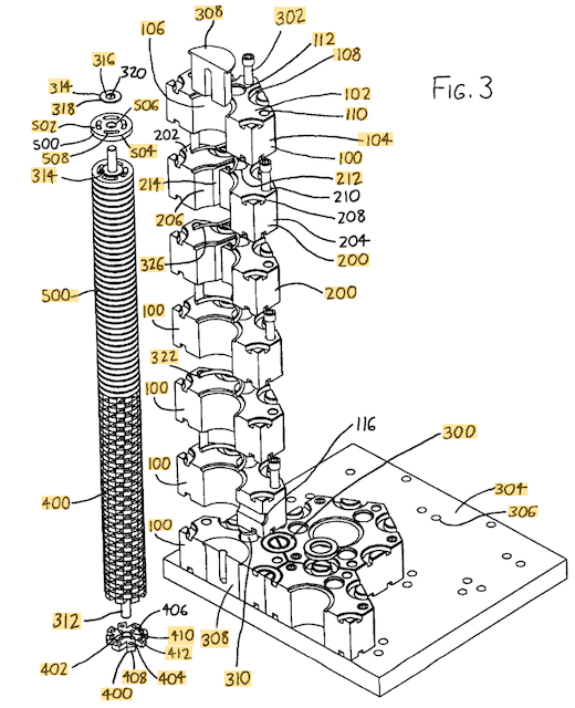
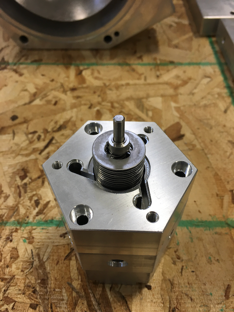
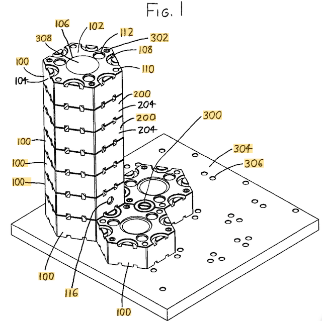
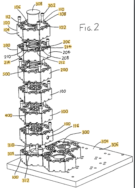
To enhance the reader's understanding, the following summary will make reference to the accompanying FIGS. 1-3, which illustrate an exemplary version of the modular fluid handling device. The device includes a number of blocks—more particularly, fluid passage blocks 100 and fluid intake/outlet blocks 200, as will be discussed below—which each include a block top face 102/202, an opposing block bottom face (not shown), and a series of block sides 104/204 therebetween. The block faces 102/202 are preferably shaped as tessellating regular polygons, whereby the blocks 100/200 may be arrayed together in side-to-side abutting relationship to form a two-dimensional array of blocks (as best seen in FIG. 1). Each block 100/200 includes a central block bore 106/206 extending between the block faces 102/202, whereby the blocks 100/200 may also (or alternatively) be arrayed together in face-to-face abutting relationship to form a stacked array of blocks wherein abutting blocks have their block bores 106/206 coaxially aligned (as seen in the stack of blocks 100/200 shown at the left side of FIGS. 1-3). The foregoing arrangement allows a user to horizontally array and vertically stack blocks 100/200 together into some desired arrangement which is suitable for the user's intended use, e.g., for purposes of experiment, prototyping, or production.The blocks 100/200 include some means for allowing horizontally adjacent blocks 100/200 to be affixed together, with a preferred horizontal affixment means being best seen in FIG. 3. Here, the block faces 102/202 include semi-annular depressions 108/208 extending from the block sides 104/204, whereby adjacent blocks 100/200 arrayed together in side-to-side abutting relationship may receive an annular side fastener 300 in their adjacent semi-annular depressions 108/208 to affix the adjacent blocks 100/200 together.The blocks 100/200 additionally include some means for allowing vertically stacked blocks 100/200 to be affixed together, with a preferred vertical affixment means being best seen in FIGS. 2-3. The blocks 100/200 here include face fastener openings 110/210 in their block faces 102/202, with the face fastener openings 110/210 being situated such that blocks 100/200 situated in face-to-face stacked relationship have their face fastener openings 110/210 coaxially aligned. This arrangement allows the blocks 100/200 to be affixed together in face-to-face abutment by extending a fastener 302 between the aligned face fastener openings 110/210 of the abutting blocks 100/200.To provide a stable base for a fluid handling device assembled from a series of blocks 100/200, a mounting plate 304 is preferably provided upon which the affixed blocks 100/200 may rest. The mounting plate 304 has a mounting surface with plate fastener openings 306 arrayed therein, such that when several blocks 100/200 are received thereon in side-to-side abutting relationship, the plate fastener openings 306 coaxially align with the block face fastener openings 110/210. Fasteners 302 can then be extended through the block face fastener openings 110/210 and into the plate fastener openings 306 to affix a block to the mounting plate 304.One or more of the blocks then takes the form of a fluid passage block 100 (see particularly FIGS. 2-3), wherein each fluid passage block 100 further includes one or more fluid passages 112 which extend between the opposing block faces 102, and which are situated between the block bore 106 and the block sides 104. These fluid passages 112 are preferably regularly arrayed about the block bore 106 such that a stacked array of fluid passage blocks 100 having their block bores 106 coaxially aligned will also have their fluid passages 112 coaxially aligned, such that fluid may travel between the fluid passages 112 of adjacently stacked fluid passage blocks 100.One or more of the blocks also preferably takes the form of a fluid intake/outlet block 200 which includes the features of a fluid passage block 100 (i.e., it includes fluid passages 212 similar to the fluid passages 112 described above), but also includes ducts 214 extending from the fluid passages 212 to the block bore 206, whereby fluid may travel between the fluid passages 212 and the block bore 206. These ducts 214 may assume a variety of forms, but are preferably formed as shown in FIGS. 2-3, wherein the ducts 214 are defined as slotted openings which extend from the block bore 206 to the fluid passages 212. These ducts 214 are preferably oriented in directions extending both radially and tangentially with respect to the block bore 206, and which also extend between the opposing block faces 202 in a direction oriented along the axis of the block bore 206. By orienting the ducts 214 in an at least partially tangential direction (i.e., in an at least partially clockwise or counterclockwise direction), and by providing all ducts 214 with the same tangential orientation, fluid flowing from the fluid passages 212 to the block bore 206 (or conversely flowing from the block bore 206 to the fluid passages 212) will assume a circular or whirling motion in the block bore 206, which is useful for reasons discussed below.The arrangement described above provides for axial flow of fluid between stacked blocks through the block bores 106/206 and/or fluid passages 112/212 (and ducts 214), as well as radial flow within a fluid intake/outlet block 200 between the fluid passages 212 and block bores 206 via the ducts 214. Fluid flow between horizontally adjacent blocks 100/200 can also be provided by channels—exemplified by channel 116—which extend from a block bore 106/206 to a block side 104/204, so that fluid may flow between adjacently aligned channels 116 in adjacent blocks. (Since only a single such channel 116 is illustrated in the accompanying drawings, the channel 116 can be regarded as a fluid input port, or a fluid output port, for its fluid passage block 100 to allow entry or exit of fluid to the stacked blocks 100/200.) Additionally, plugs may be provided in block bores 106/206 and/or in fluid passages to block the passage of fluid where desired. As best seen in FIGS. 2-3, bore plugs 308 are situated within the block bores 106 of the top and bottom fluid passage blocks 100 of the stack to prevent fluid flow within these block bores 106, and passage plugs 310 are provided within the fluid passages 112 of selected fluid passage blocks 100 to prevent fluid flow within these fluid passages 112. With the arrangement depicted in the drawings, it can be seen that fluid entering the channel 116 will flow into the central block bore 106 of its fluid passage block 100, up the block bores 106 of the fluid passage blocks 100 stacked above, into the block bores 206 of the fluid intake/outlet blocks 200 stacked above, and then into the ducts 214 and fluid passages 212 of these fluid intake/outlet blocks 200. The fluid can then exit the fluid passages 112 of the fluid passage block 100 at the top of the stack. (It should be understood that this is only an exemplary fluid flow arrangement, and that by arraying blocks 100/200 differently, different arrangements can be obtained.)Various components may then be provided to allow pumping of fluid through the fluid passage blocks 100 and/or fluid intake/outlet blocks 200, or to allow fluid power to be derived from fluid flowing through the fluid passage blocks 100 and/or fluid intake/outlet blocks 200. An elongated shaft 312 (FIG. 3) may be centrally mounted within the block bores 106/206 of one or more blocks to extend along the axes of the block bores 106/206. As best shown in FIG. 3, the ends of the shaft 312 are mounted within the bore plugs 308 at the top and bottom fluid passage blocks 100 of the stack to maintain the shaft 312 at an orientation extending along the axes of the block bores 106/206 of the fluid passage blocks 100 and fluid intake/outlet blocks 200. The shaft 312 may then bear star wheels 400 and/or rotor discs 500—best seen in FIG. 3, wherein several star wheels 400 are shown stacked on the shaft 312 alongside a stack of rotor discs 500—to provide pump and/or turbine action. Each of the star wheels 400 and rotor discs 500 will now be discussed in turn.Looking to FIG. 3, each star wheel 400 includes a central hub 402 with several vanes 404 extending therefrom, with opposing wheel faces 406 axially bounding the hub 402 and vanes 404 and an outer wheel circumference 408 radially bounding the vanes 404. The wheel circumference 408 is sized to be complementarily received within the block bore 106/206 of one of the blocks 100/200 so that a star wheel 400 may rotate within the block bore 106/206 with the wheel circumference 408 resting closely adjacent the walls of the block bore 106/206. A wheel bore 410 is centrally defined in, and extends between, the wheel faces to receive the shaft 312. Each star wheel 400 may therefore rotate about (or with) the shaft 312 as fluid flows within the block bore 106/206 to impel the vanes 404 in a circular direction, or to allow the vanes 404 to impel fluid in a circular direction. FIG. 3 illustrates the stack of star wheels 400 as having the vanes 404 of the star wheels 400 staggered within the stack, such that each star wheel 400 has its vanes 404 vertically bounded by the spaces between the vanes 404 of the adjacent star wheel(s) 400 (and conversely, each star wheel 400 has the spaces between its vanes 404 vertically bounded by the vane(s) 404 of the adjacent star wheels 400). As a result, fluid cannot flow vertically between adjacently stacked star wheels 400 unless apertures 412 are defined in the vanes 404, with the apertures 412 extending between the opposing wheel faces 406. The apertures 412 thereby allow fluid to flow vertically through a star wheel 400, as well as driving the star wheel 400 (or being driven by the star wheel 400) circularly within the block bore 106/206. The star wheels 400 need not have vanes 404 which are oriented solely in radial directions with respect to the wheel bore 410 (i.e., in “paddlewheel” fashion), and vanes 404 may be angled tangentially as well as radially (i.e., in “pinwheel” fashion), with all vanes 404 angled in clockwise or counterclockwise directions, to help impart the star wheels 400 with preferential directions of spin (at least at startup).Also looking to FIG. 3, the rotor discs 500 each have opposing disc faces 502 axially bounding each rotor disc 500, an outer disc circumference 504 radially bounding the disc faces 502, and a disc bore 506 centrally defined in (and extending between) the disc faces 502 for receiving the shaft 312. The disc circumference 504 is preferably sized to be complementarily received within the block bore 106/206 of one of the blocks 100/200 so that a rotor disc 500 may rotate within a block bore 106/206 with the disc circumference 504 closely spaced adjacent the wall bounding the block bore 106/206. One or more disc fluid passages 508 are then situated between the disc bore 506 and the disc circumference 504 to extend between the opposing disc faces 502, thereby allowing fluid flow between the disc faces 502. As a result, when rotor discs 500 are stacked in spaced relation and fluid is directed axially through the disc fluid passages 508, with the fluid being able to flow radially outwardly between the spaced discs 500 (as it can in the accompanying drawings, wherein radially outwardly flowing fluid may exit the ducts 214 in the fluid intake/outlet blocks 200), the rotor discs 500 will be driven by the fluid to rotate owing to surface adhesion/boundary layer flow effects (a phenomenon noted by Nikola Tesla, and utilized to similar effect in Tesla's U.S. Pat. No. 1,061,142). Conversely, rotation of the shaft 312 and rotor discs 500 can be used to pump fluids.To space the rotor discs 500 apart, spacers 314 are also preferably provided. Each spacer 314 has opposing spacer faces 316 which axially bound each spacer 314, an outer spacer circumference 318 radially bounding the spacer faces 316, and a spacer bore 320 extending between the spacer faces 316 wherein the shaft 312 may be received. The spacer circumference 318 is preferably sized with a radius less than the radius between the disc bore 506 and the disc fluid passages 508, so that a spacer 314, when situated on the shaft 312 between a pair of rotor discs 500, will not block fluid flow between the disc fluid passages 508 of the spaced discs 500.By suitably arranging the foregoing fluid passage blocks 100 and fluid intake/outlet blocks 200 (as well as any of the blocks described in U.S. Pat. No. 7,146,999 to Giese), as well as plugs 308/310, shafts 312, star wheels 400, rotor discs 500, spacers 314, etc., a user can generate a wide variety of fluid pumping and/or fluid power arrangements. To illustrate, in the arrangement of the accompanying drawings, fluid may enter the channel 116, flow axially upwardly in the block bores 106 of the fluid passage blocks 100 and also upwardly through the vane apertures 412 of the star wheels 400 therein, and then flow axially upwardly within the block bores 206 of the fluid intake/outlet blocks 200. Within the fluid intake/outlet blocks 200, the fluid may flow through the disc fluid passages 508 of the rotor discs 500, as well as radially outwardly between the spaced rotor discs 500, to enter the ducts 214 and fluid passages 212 of the fluid intake/outlet blocks 200. The fluid may then exit the fluid passages 112 of the top fluid passage block 100. The fluid can either be driven along the foregoing paths if the shaft 312 and one or more of the star wheels 400 and rotor discs 500 are driven to rotate, or alternatively the fluid can drive the shaft 312, star wheels 400, and/or rotor discs 500 if a suitable pressure difference is present between the points of fluid input and output.Further advantages, features, and objects of the invention will be apparent from the remainder of this document in conjunction with the associated drawings.
|


